Cart-Pole in Hardware: State Estimation and Real-Time Control
Built the inverted pendulum on a rail, read its state off quadrature encoders, and balanced it from an embedded control loop.
2024 · CSCI 5143 Real-Time and Embedded Systems, University of Minnesota · created with Kuba Kedzior
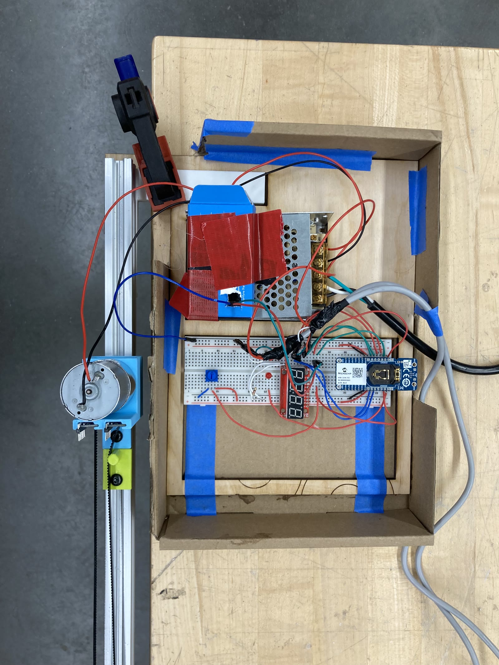
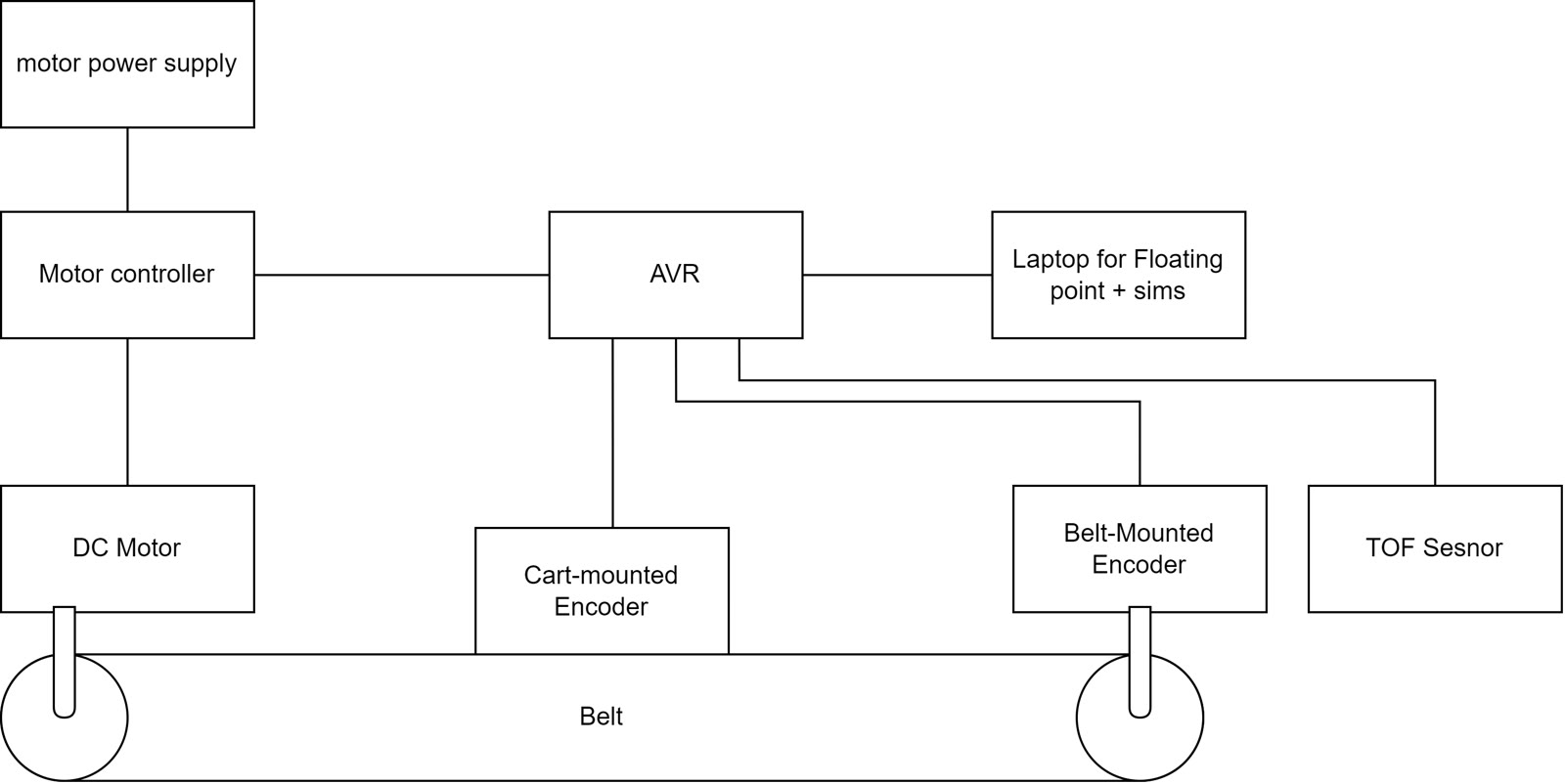
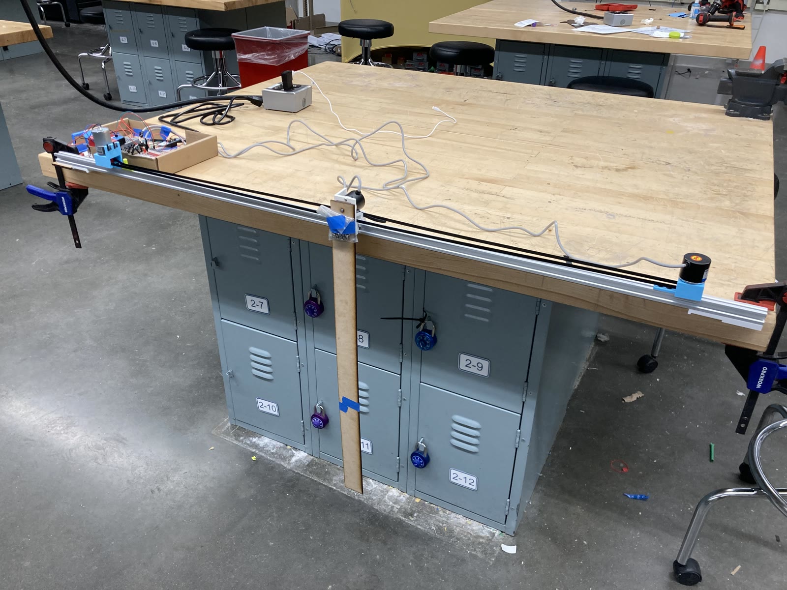
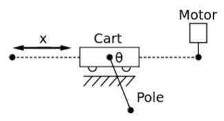
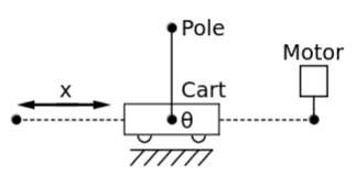
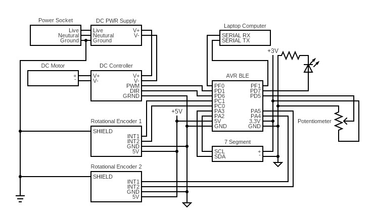
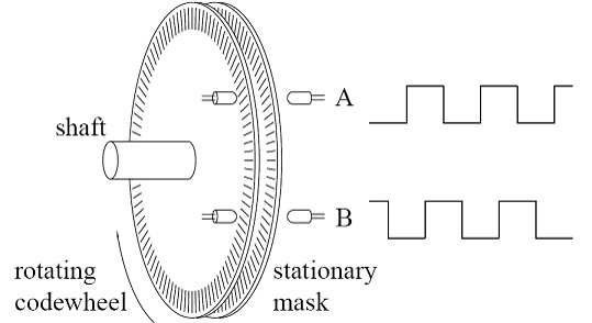
A cart-pole balancer built from parts for a real-time embedded systems course. A DC motor drives a cart along a rail through a belt and pulley, and a pendulum hangs freely from the cart. We built the rail and drive, the motor driver and sensing circuit, the quadrature decoding that turns two encoder signals into an angle, and the real-time loop that moves the cart to keep the pendulum upright. The system is modelled in state space over cart position, cart velocity, pendulum angle, and angular velocity. An AVR microcontroller running embedded C reads the sensors, and a laptop runs the floating-point control. The pendulum balances under PID control.
My role
Derived the state-space model, wrote the quadrature decoding and the real-time control loop, and built the encoder and motor-driver circuit.
Results
The balancing controller works, under PID rather than the LQR originally planned. The limiting factor was sensor drift. The optical encoders are precise but accumulate error, their datasheet warns that vibration causes misreads, and mounting one on a moving cart supplied exactly that. Once the estimated angle drifts there is no way to detect or recover it in software, which leaves the controller without the state it needs. Fixing it means adding a drift-free Hall effect sensor and fusing it with the encoder through a complementary or Kalman filter. We dropped the swing-up controller for the same reason.
Media